


© Lee Christopher 2003-2024
A Pair of Modernized
McCloud SD38s
Resurrected from the
Future Projects Bin
Upgrading an Older Locomotive Model to Represent a Different Model and
Time Frame
By Lee Christopher - all photos are by the author
Published in part in the November 2009 issue of Model Railroader magazine
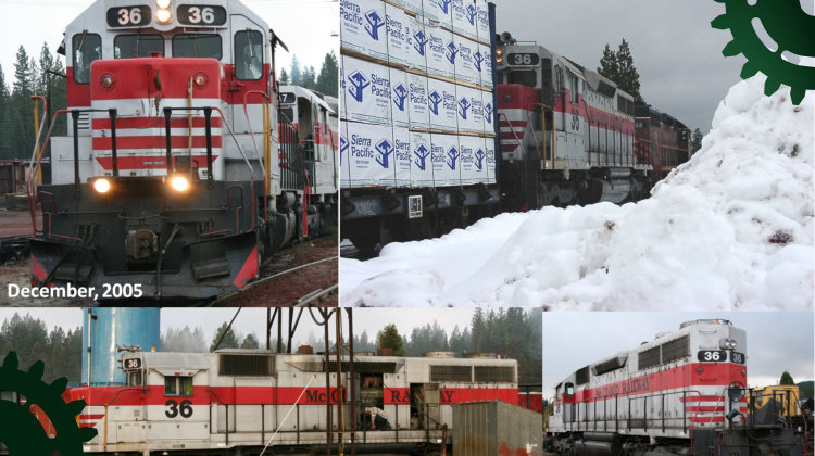
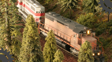
In early May of 1969, GM-EMD delivered three brand new SD38s, numbered 36–38, to Northern California’s McCloud River Railroad (predecessor to the present day McCloud Railway, a class III short line). The locomotives have since remained as part of the McCloud (except for an occasional lease-out to the SP) hauling forest, paper and mining products as well as occasional agricultural and other goods. They have had a few paint schemes over the years along with some configuration changes that include various snow plows, larger fuel tanks, added sump drainage tanks and the addition of modern ditch lights. As of this writing, these prototypes are still in service pulling the McCloud Railway’s elegant Shasta Sunset Dinner Train over portions of the last remaining 16 miles of McCloud mainline trackage that connects via a switchback the town of McCloud with the Union Pacific in Mount Shasta City. Before Athearn came out with their HO models of this type there was a need for two more SD38s for the author’s ongoing McCloud Railway layout project that’s currently a little better than 50% complete. Although it’s been around awhile, the Kato SD40 (reviewed in MR September, 1991) seemed like an excellent starting point to kit-bash these models with its similarity in appearance and quiet, silky-smooth running mechanism. A pair of these undecorated engines were purchased but due to competing priorities, they remained untouched in the “future projects” bin for some time. The kick in the proverbial shorts was participation as part of the layout tours associated with the 2008 NMRA National Convention in Anaheim, CA that had made it clear that this model railroad was in serious need of more motive power! The modest SD40 vs. SD38 differences, the unique McCloud particular details and internal space requirements for the lighting and electronic components meant a number of changes to the Kato SD40 models were required before the appropriate paint schemes could be applied. Hence, the inspiration for this article came from building the engine pair seen in Figure 1 hard at work on the author’s HO layout. Project Requirements Both locomotive models needed to reasonably represent the appearance, configuration, paint schemes and approximate weathering of their respective prototypes as they appeared during the summer of 1997. This includes the new (retro) red on silver paint scheme that had recently been applied to both #37 and #36 that has never been available on any commercial model. Number 38 was (and still is) wearing its subdued black, orange and white on brown scheme dating from around 1982, similar to one of Athearn’s SD38 paint schemes. The models also needed DCC, slow, smooth switching capability, LED lighting, sound, capability to pull at least nine or more weighted modern freight cars up a curving 3% grade and tolerance to the rapid track corrosion that goes along with a Southern California garage layout in a coastal salt-air environment. In short, these were not to be museum pieces, just dependable, nice to run, nice to look at, believable models of the chosen prototype and era. Getting Started Prototype reference photos are provided in Figures 2 and 3. Some of these are from considerably later than the 1997 target date, but the only notable differences other than the level of grime and weathering are some front hood nose damage evident on #36 that occurred around 1999-2000 and the spark arrestors installed over the exhausts around the same time after one of the McCloud SDs allegedly ignited an accidental but expensive forest fire. See Figures 4 through 6 for an overview of where all the details will are installed. The models were completely disassembled down to the bare frame before beginning this kit bash. Even the truck side frames were removed so the correct color side frames could be installed. The first thing noticeable when the body shells are removed is that even without the Kato light board, the clear Lucite light bar and the removable upper body metal weight, there was not enough room for the selected dual sound/loco decoders, the speaker enclosure and the various discrete resistors, capacitors, connectors, LEDs and wiring that needed to be installed (a common problem in many modern models – especially for sound installations). Frame Modifications The first frame rework is to remove material from the rear frame tower for the sound electronics. If one of the alternative Tsunami decoders mentioned in the materials list were chosen over the dual decoder Lenz and DSX used by the author, considerably less frame material removal from the rear tower would be needed. The modeler will need to tailor this internal trimming for the specific decoder installation selected. See Figure 7 Other frame mods are also required. The prototype McCloud SD38s are currently equipped with 3200 gallon fuel tanks which are shorter than the 4000 gallon tanks represented on the Kato model. In addition, the prototype’s tanks are mounted towards the rear truck in contrast to the forward mount of most 3200 gallon tanks on EMD installations (including Athearn’s model). This difference is probably due to EMD’s fuel plumbing locations associated with the original rear mounted 1200 gallon tanks that were delivered with these locomotives. The Kato metal frame/body-weight must be shortened on the front end to a 2.15 inch length as shown in Figure 8 as well as shortening the surrounding Kato styrene tank to a 2.30 inch outside length (the styrene tank details are discussed later). This is still slightly longer than the prototype but maintains plenty of strength margin in the frame and does not compromise the motor well. Both the Kato SD40 and Athearn SD38 models represent as-delivered locomotives with no ditch lights, but since ditch lights were added to the McCloud prototypes in the 1980s they are needed on these models. To begin, portions of the frame front end are hollowed and trimmed to make room for the ditch light LEDs, their brass mounting tubes and paths for the connecting wires as shown in Figure 9. Access to a Sherline miniature mill made relatively quick work of all the metal material removal from the frame but careful efforts with a jeweler’s or small hack saw, a drill, a Moto-Tool, a medium sized mill file and some small modeler’s files could certainly produce equivalent results. Electronics and Lighting This author chose to use a dual decoder installation which includes a Lenz Gold JST loco decoder with a Power-1 module which has been shown to have remarkable stay-alive capability on dirty or corroded track along with a Soundtraxx DSX (sound-only) decoder that was boosted with extra capacitors for good stay-alive ability. There are now more choices for single decoder installation options so more compact solutions are feasible than the one described and shown in this article, especially for operations in less corrosive environments. Planning, measuring the available spaces and frequent test fitting as you go are important as the spaces above the mechanism inside a modern HO loco model are usually already occupied with a circuit board with a DCC connector and LEDs, light bars, frame weight and other components. Standard T1 (3mm dia) warm white LEDs can work just fine for the 1.8mm diameter lighting needed for most second generation and later diesel equipment. Previous MR contributors have shown that as long as the modeler is careful to avoid cutting into the metal LED components, the outside diameter of the upper (lens) portions of the clear plastic can be ground away by spinning the LED in a drill chuck or a small lathe and touching the side of the LED carefully with a fine modeler’s file as shown in Figure 10. Some checks using a sample LED, a voltmeter across the LED leads, a first guess for the series resistor (usually around 1000 Ω) and the designated light function output from the decoder selected by the modeler is highly recommended. This provides an opportunity to fine tune the resistor value for appropriate LED brightness and to verify that the voltage across the LED doen’t exceed limits. For this author’s application, one ½ watt 910 Ω resistor in series with each of the six LEDs provided an appropriately limited input voltage and a realistic level of brightness for the sealed beam lighting used in diesels of this era. To minimize light leakage through the styrene body from the bright LEDs, 3/32 brass tubing was mounted on the front of the frame for the ditch lights and was fitted through the pilot to provide a light guide/shield. The tubing will need to be drilled out with a #49 bit with the turned-down LEDs inserted into the rear of each tube with the outside of the tubes filed to represent each light housing (including the dual cab headlight shades on the prototypes). The front of the Kato pilot/walkway will need to be drilled out so that the pilot will tightly slide over the ditch light tubes on the frame. For the cab and rear hood lights the model’s styrene headlight mounts/openings were drilled out with a #41 bit and replaced with the aforementioned tubes. For all six lights, a section of 1/16 diameter clear Lucite rod is used as a light pipe between the front of the LED and the headlight face. A small rectangle of punchboard normally used for circuit design and testing was cut to the approximate dimension of the original Kato light board and was screwed onto the light board mounting posts (an extension of the motor mounts) after those posts had been trimmed down to provide adequate vertical clearance between the decoder and power module and the underside of the body shell. This provided a mounting surface for the Lenz decoder electronics and would likely be suitable for other decoder selections as well. Miniatronics Micro-Mini connectors were used between the track power from the trucks and each of the frame mounted decoders as well as from the decoders to the lighting in the loco shell. This provided a way to electrically isolate each decoder for totally separate CV programming if needed and provided for complete separation of the shell when needed. Note that these connectors are only rated at one amp so while they are adequate (barely) for the low motor current of this Kato model, other options would be advised for use with higher current applications. The electronics installation is shown in Figure 11. Body External differences include rooftop radiator fans (three on the SD40 vs. two on the SD38), rooftop dynamic brake fans (smaller on the SD38), prime mover exhausts (one large for the turbocharged EMD 16-645E3 prime mover in the SD40 vs. two small exhausts on the non-turbo 16-645E in the SD38), radiator side grills (slightly smaller on the SD38) and the manual brake. All of these must be removed (or filled) and replaced on the Kato body shell. The SD40 roof top exhaust, the side radiator grills at the rear of the long hood and the recessed hand brake on the left side of the short hood are all trimmed flush with the body with a sharp flat blade tool, filled and sanded smooth as shown in Figure 12. Cut-outs for the radiator side grills were then cut per Cannon and Company instructions. Next, a 0.73 x 1.70 in. section around the three roof-top radiator fans and a 0.61 x 1.26 section around the two dynamic brake fans were removed to facilitate the replacements. Where feasible the removal / replacement roof sections should follow the lines of existing body roof details to help minimize the seams. Most of the Kato body roof is about 0.060 inches thick so using some Evergreen 0.030 sheet from the scrap box a double layer was made for the replacement roof sections as shown in Figure 13. The holes were cut at the proper size and spacing as shown first, then the roof sections were cut out and filed smooth. These replacement roof sections will need to be glued in place as shown in Figure 14 before adding the fans so the seams can be filled and smoothed to avoid damaging these delicate Canon detail assemblies. Building the Fuel Tank The fuel and air reservoir tanks were modified to reflect the McCloud configuration and to fit the trimmed frame. The left and right side Kato tank halves that fit around the tank portion of the frame were first cut long ways to remove the molded-on air tanks and then cut in half (short ways), trimmed to fit together at a total tank length of 2.30 inches (not including added details) and re-attached together using a bit of scrap styrene on the inside to provide additional strength. The left and right halves were similarly joined after the protruding latching tabs were removed. Model builders putty was used to smooth over the seams prior to final sanding. The Canon air reservoir tanks, fuel tank fillers and various plugs and vents were then assembled and added. Holes in each reservoir tank end will be needed so that brass wire can be inserted through the tank to simulate the air lines. Retrofitting of an external tank presumably for collection of fluid leakage from around the prime mover began to appear on the McCloud SDs around 1996. This was fabricated from 0.125 styrene rod and strips, a couple of spare fittings from the Cannon tank detail kit and installed horizontally across the upper rear of the fuel tank similar to the prototype. Some care with the length of this tank is needed as there can potentially be interference with motion of the rear truck, especially if operation on relatively sharp curves is anticipated. The assembled fuel tanks were airbrushed black to match the frame and weathered prior to gluing them onto the frame. Be sure that the walkways will fit flat over the Canon air reservoirs – those reservoirs may need to be flattened slightly with a file across the top if there is interference. Detailing The Kato model includes separate engineering plastic grab irons to be added by the modeler but these are a bit oversized so they were replaced with thin (0.008” dia) wire metal grabs. The existing holes in the shell can still be used but additional #80 holes will be needed for mounting the long hood curved roof grab onto the replacement roof section and for the two grabs on the top and bottom of the number board of #36. A narrow strip of scrap 0.030 inch sheet styrene makes a handy temporary spacer for keeping grab irons aligned at the proper distance from the shell until the CA sets up. Be sure to bend over and trim the protruding wires inside the body shell so they don’t interfere with fitting the shell over the drive mechanism and electronics! Most of the remaining detailing with the commercial components is pretty straightforward at this point. If you want to hang (or lay) some MU cables on your engines, they can be made from 0.012 brass wire and some 0.030 styrene rod. With some careful work on the rod end using a #80 bit, drill a hole for the wire, cone the edge of the rod, CA the wire in place and trim off the unwanted styrene. Once the electronics and lighting are selected, installed and tested and most of the body mods and detailing completed, some of the weight previously removed to make room for everything can now be replaced with carefully located lead sheet judiciously placed in remaining spaces. Paint, Decorating and Weathering There are a number of web sources for reference photographs of McCloud motive power but the premier site for current as well as historical information on all aspects of the railroad is Jeff Moore’s McCloud Rails at http://www.trainweb.org/mccloudrails/index.html. There are numerous photos covering the appearance and operation of these locomotives from factory fresh to near present day. The red on silver paint for engine #36 was just a few months old in the summer of 1997 so only very light weathering was needed after paint and decals. The damage to the nose of #36’s short hood evident in the photos happened around 1999-2000 so no attempt was made to include it. By 1997, number 38’s paint had seen 15 years of pushing plows though heavy winter mountain snows and straining with heavy loads over the 4%+ grades and 15º curves with lots of exposure to gritty volcanic ballast, dust and exhaust. The “McCloud River Railroad” name had been cut from the top of the McCloud herald on the cab side and new lettering had been applied below it denoting the new “McCloud Railway” road name in white lettering. Both models remained completely disassembled for painting, decorating and weathering. The color mixes are as given below. These were thinned and applied with an airbrush with appropriate areas masked as needed to build the striping and color sections. A light spray of Testors Glosscoat was applied after the color coats to provide a smooth shiny finish for decal application. Dullcoat was applied as a decal sealant and as a first step in weathering after the decals had been applied. This author found out the hard way that neither lacquer nor acrylic based paints will stick to the engineering plastic handrails on the Kato models despite careful cleaning. Even a bit of gentle sanding with 600 grit didn’t help! Thanks to experienced friends in the Los Angeles Model Railroad Society, the author was steered toward paints developed for the slot car hobby and the Lexan model car surfaces. There are a few choices here but the Faskolor line from Parma worked well and was reasonably priced. These excellent water based paints would have worked well for the entire model although the color selection appears to be limited. Weathering on both models included (in differing degrees) blackening the grills and fan screens, a few brown streaks showing the ever present battery leakage near the front just below the battery boxes, using some highly diluted weathered black around the various access covers/doors and hinges and some additional rust and dirt coloration on the trucks. Evidence of wheel bearing changes were included by painting selected journals with contrasting colors as on the prototype. Varying amounts of diluted weathered black and brown oversprays were used to further dull and blend the colors. #38 roof and under frame: Floquil Engine Black #38 body: 4 parts Floquil So. Freight Car Brown 2 parts Floquil Roof Brown 1 part Floquil Reefer White #38 upper body dividing stripe: Floquil Reefer White #38 front/rear safety stripes: 3 parts Floquil CN Orange 1 part Reefer White #38 cab interior: Floquil Depot Beige #38 railings: Parma Fasorange #36 underframe: Floquil Engine Black #36 body: Floquil Bright Silver #36 body band: Floquil ATSF Red #36 front/rear safety stripes: Floquil Reefer White #36 cab interior: Floquil Depot Beige #36 railings: Parma Fasblack and Fasred Acknowledgements: This author owes a debt of thanks to Mr. Jeff Forbis and the McCloud Railway crews and staff who have all been most kind, generous and accommodating in providing access to and information regarding McCloud equipment, facilities and operations over numerous visits throughout the past 14 years. This author extends a very special thanks to Mr. Jeff Moore, a true expert on the history of the McCloud railroads who has provided countless invaluable prototype specific facts, details, data, ideas and other information. Many thanks are also given to model railroading friends for their encouragement, ideas and support including friend and fellow McCloud modeler Mr. Drew Toner and the membership of the Los Angeles Model Railroad Society. Prototype References for the McCloud Railway and McCloud River Railroad Hanft, Robert M., Pine Across the Mountain – California’s McCloud River Railroad, 1971 and updated in 1990. Moore, Jeff, Images of Rail - Rails Around McCloud, 2008. Links McCloud Rails - Jeff Moore’s outstanding site includes many more links and references as well as abundant photographs and information.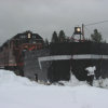
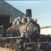
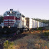


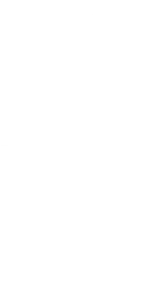
Figure 1. Prototype McCloud Railway SD38 #36 in McCloud, CA captured in 2003 through 2008
Additional text needed?

McCloud Railway